
How to Install a Motion-Sensor Light Switch in a Stairway
About This Project
This project outlines the steps for installing a motion sensor light switch to automate lighting in a stairway. It covers preparation, wiring, mounting, and testing the new switch.
Tools & Materials
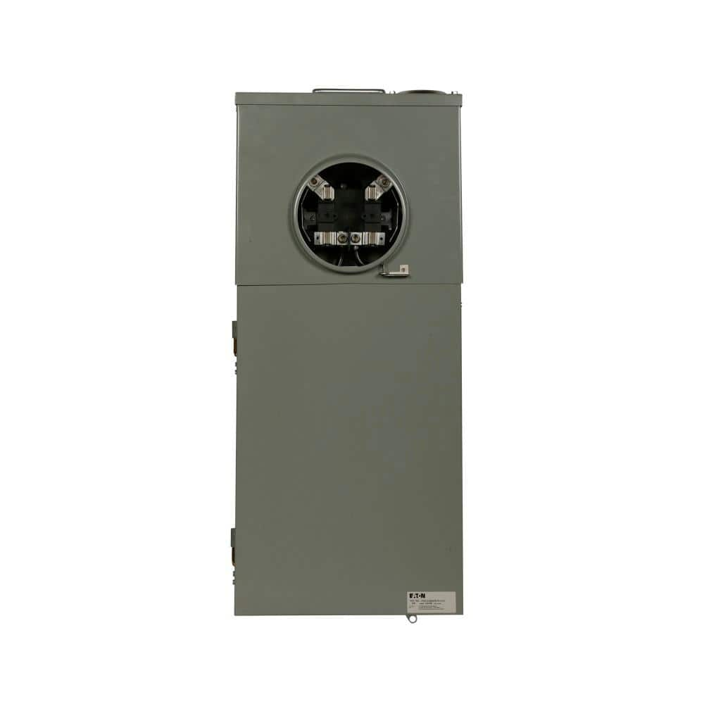
Eaton CH 200 Amp 12-Space 12-Circuit Non-EUSERC Meter Breaker Panel CMB1212B200BTS
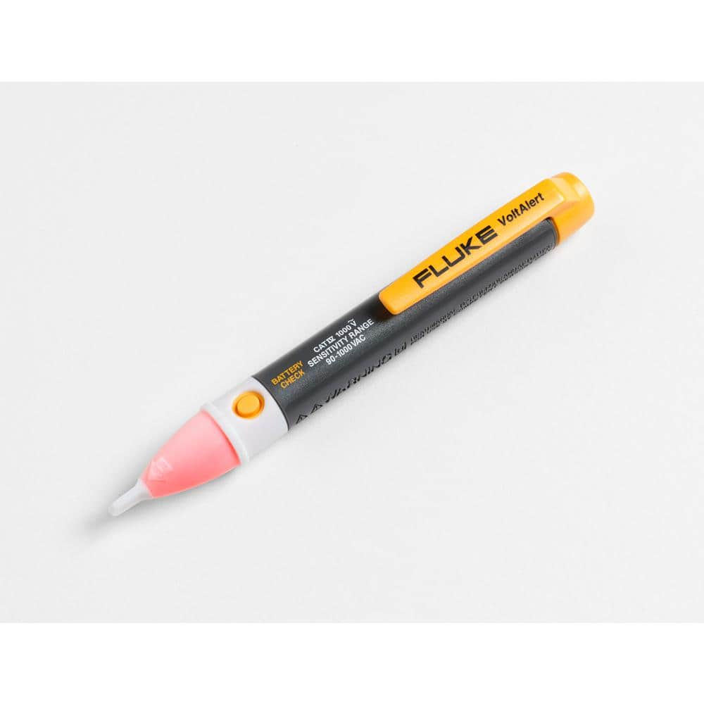
FLUKE 1AC-A1-II VoltAlert Non-Contact Voltage Tester 2432932
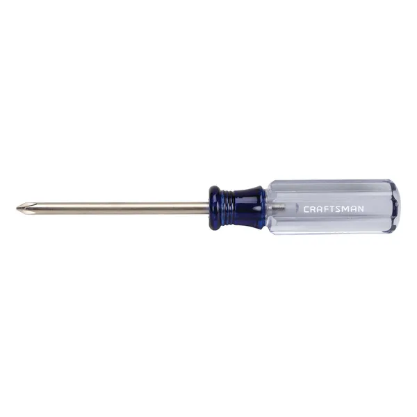
Phillips head screwdriver
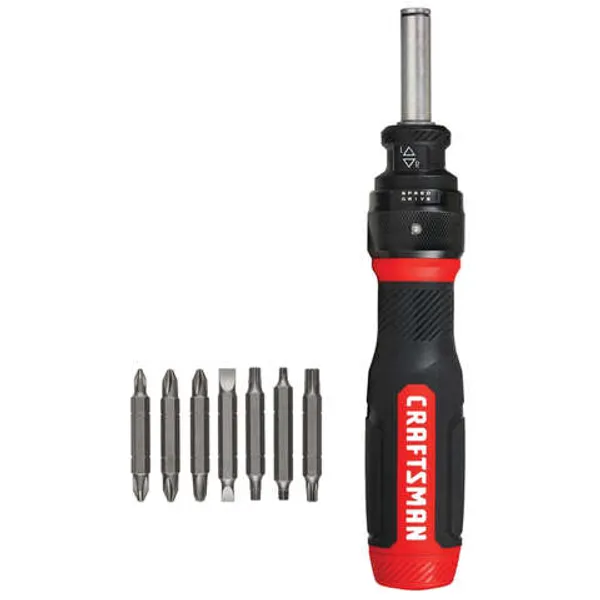
Screwdriver

CityPost 8 ft. Stair Cable Railing in White CP-8-W-S

Wire nuts
Eaton CH 200 Amp 12-Space 12-Circuit Non-EUSERC Meter Breaker Panel CMB1212B200BTS
Eaton's residential meter breakers are service entrance equipment systems that consist of a single meter socket and load center distribution section. This type of configuration is also known as All-in
FLUKE 1AC-A1-II VoltAlert Non-Contact Voltage Tester 2432932
The portable 1 AC II non-contact voltage tester from Fluke are easy to use - just touch the tip to a terminal strip, outlet or supply cord. When the tip glows red and the unit beeps, you know there's voltage present. Electricians, maintenance, service, safety personnel and homeowners can quickly test for energized circuits in the workplace or at home and even detect miswires of an electrical outlet.
Phillips head screwdriver
This is a type of screwdriver that has a cross-shaped tip.
Screwdriver
A tool used to turn screws.
CityPost 8 ft. Stair Cable Railing in White CP-8-W-S
CityPost 36 in. tall cable railing kits can be ordered to fit your needs regardless of your project layout. All kits come with enough posts to install at a maximum center-to-center spacing of 6 ft. (example:
Wire nuts
Connects electrical wires with a twist.
Steps

Turn Off Power
5 minutesLocate the circuit breaker that controls the stairway light. Flip the breaker to the 'OFF' position. It is crucial to verify that the power is off by attempting to operate the existing light switch. If the light does not turn on, the power is successfully cut.
Watch: Cut Power at Circuit Breaker
Remove Existing Switch Plate and Switch
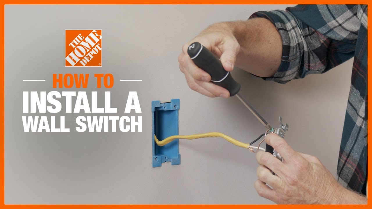
10 minutesUnscrew and remove the cover plate of the existing light switch. Then, unscrew the old light switch from the electrical box. Carefully pull the switch out from the box to expose the wiring. Note or take a picture of how the wires are connected to the old switch.
Watch: Remove Existing Switch Plate and Switch
Identify and Disconnect Wires
10 minutesExamine the wires connected to the old switch. Typically, you will find a 'line' wire (power coming in), a 'load' wire (power going to the light), and a 'ground' wire (bare copper or green). Loosen the terminal screws or release the wires from the push-in connectors on the old switch. Ensure the wires are not touching each other or the metal electrical box.
Watch: Identify and Disconnect Wires
Connect Motion Sensor Switch - Line and Load
15 minutesRefer to the wiring diagram provided with your motion sensor switch. Connect the 'line' wire (power source) to the terminal or wire designated for 'line' or 'input' on the new switch. Connect the 'load' wire (to the light fixture) to the terminal or wire designated for 'load' or 'output' on the new switch. Ensure connections are secure.
Watch: Wire the New Motion Sensor Switch

Mount the Motion Sensor Switch
10 minutesGently fold the connected wires back into the electrical box, ensuring they are not pinched. Align the mounting screws on the new motion sensor switch with the corresponding holes in the electrical box. Screw the switch into place until it is snug against the wall.
Watch: Mount Motion Sensor Switch
Restore Power and Test
10 minutesReturn to the circuit breaker panel and flip the breaker back to the 'ON' position. Wait a few moments for the motion sensor to calibrate if required by the manufacturer. Walk into the area covered by the sensor to test if the light turns on automatically. Verify that the light turns off after the set period of inactivity.
Watch: Restore Power and Test Functionality